Many machinists, especially brand new and hobby machinists, probably think performance and tool life don’t go hand in hand. You choose one or the other and let the chips fall where they may (sorry!). But it turns out that there is actually a middle ground that’s good for both performance and tool life, and it’s your job as machinist to find that “Goldilocks” Feed and Speed combination that is neither too fast nor too slow.
The Parable of Goldilocks and the Three Vertical Machine Centers
As you recall, Goldilocks was out wandering in the woods, lost, and getting increasingly desperate to find a CNC Shop willing to hire another operator. Just when she thought she couldn’t stand it any longer, she came upon a large workshop in the woods. The sign said, “Three Bears Job Shop, Inc.”, but there didn’t seem to be anyone around and the door was unlocked, so she went in.
Inside, she found three Vertical Machining Centers. Each had a workpiece loaded in a machining vise and a g-code part program all set up and ready to go. Goldilocks was delighted, and she promptly went up to the first VMC and pressed the green start button.
Goldilocks stepped up to the first VMC and pressed the green start button…
As soon as she pressed the button the machine leaped into action. The spindle wound up to the most incredibly fast rpm speed ever. Then, the cutter dove towards the workpiece at a breakneck pace, sunk it’s teeth in, and chips were flying like machine gun bullets. For just a very short time. Then Goldilocks had to duck as the endmill broke and the broken piece went sailing past her golden locks.
“Well, this can’t be right, this machine was just too fast!” she said as she strode on to the next machine.
She pressed the green button there too, and the spindle woke up, but this time it kept to a leisurely pace. Then the cutter moved towards the workpiece, again at a very slow and leisurely pace. It bit into the work ever so slightly, but kept the cut width very very small. It made it a little further than the first machine, but suddenly there was a loud “ping” and a piece of broken endmill smacked into the enclosure window right in front of Goldilock’s face.
“Darn,” she said. “That machine was too slow and didn’t work much better than the one that was too fast.”
By now, she was starting to feel a little desperate, having run two of the three machines without much success. So, she walked over to the last VMC and pressed the green button with one hand, while keeping fingers crossed with the other.
This machine’s spindle sang to life at an rpm range somewhere between what the other two had run. The cutter moved towards the workpiece quite a bit faster than the too-slow-VMC, but yet still slower than the too-fast-VMC. It bit into the material as Goldilocks held her breath and kept her palm hovering quite near the E-Stop switch in case of another broken cutter.
But this cutter kept on going through the workpiece, making tons of curly blue chips, all the while dancing and pirouetting in that certain way all HSM toolpaths share. Goldilocks was delighted, and exclaimed, “Why this VMC is Just Right!”
The End
What Really Happened to Goldilocks and Her 3 CNC Machines?
Are you like me? Do you sit through the credits hoping to get that little end of movie tidbit that is sometimes there? Good! Because in this tidbit I want to explain what was happening to Goldilocks and the Three Feeds and Speeds.
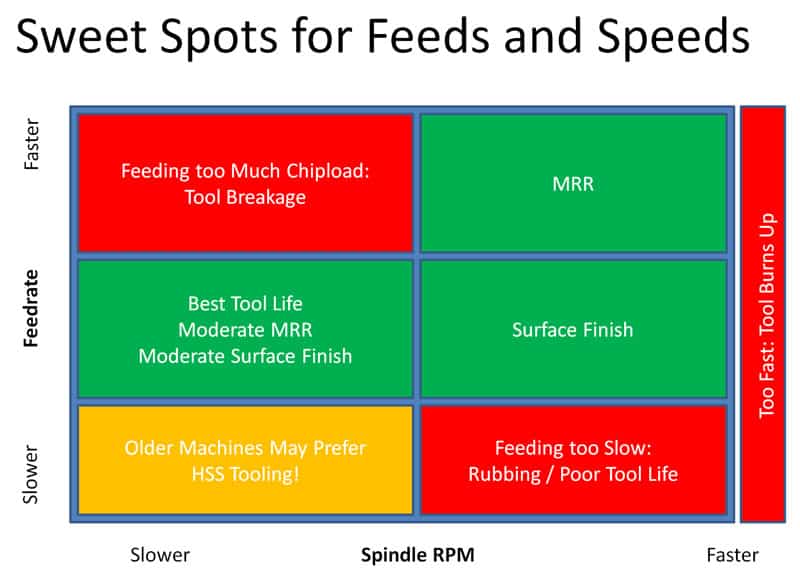
First, if you’ve ever checked out our Free Feeds and Speeds Tutorial, you’ll be familiar with the idea that Feeds and Speeds have a Sweet Spot:
What I like about this diagram is it tells you what happens if you go too fast or too slow on feedrate, spindle rpm, or a combination of both.
We can see that on that first machine, which went too fast, Goldilocks either had too much chip load (too high a feedrate relative to rpms) and broke the tool, or she ran too many rpms which got the tool too hot. Once a tool is running too hot, the edge softens, then dulls, and a broken cutter is not far behind. This latter scenario is a form of tool wear called “plastic deformation” which is to be avoided where possible.
Let’s understand briefly why those things happen.
The faster we feed, the fatter the chips we’re cutting. Fatter chips are a great idea because we remove material faster and the fat chips can carry away a lot of heat. That’s all great right up until the chips are too fat and coming off too fast. When that happens, they completely fill up the flutes of the endmill, it jams, and typically it snaps off. This usually happens pretty early in the cut, although sometimes things change in mid cut and we wind up with the same effect.
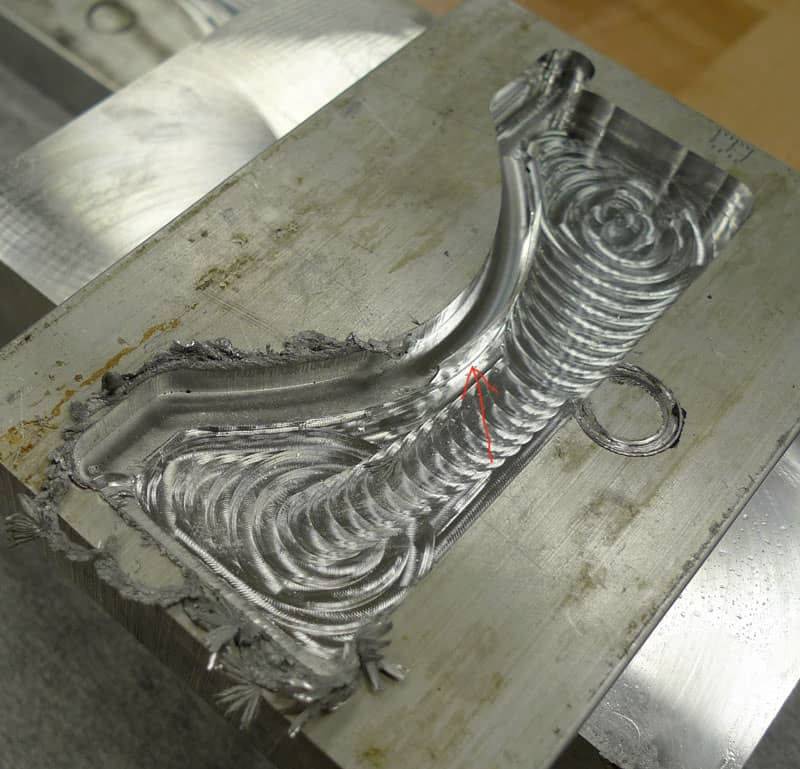
For example, too much deflection caused this cut to fail when the deflection allowed a small wall to develop that prevented coolant from going where it needed to go:
Red arrow points to the wall that developed and ultimately killed the cutter…
In the end, it’s pretty obvious that too much speed, whether rpms or feedrate, kills cutters.
But what about that machine that was too slow? How in the heck did that hurt the cutter?
Many machinists believe that slowing things way down and reducing cut widths will “baby” the cutter so it lasts much longer.
But, in the odd world of cutting tool physics, this can be one of the worst things you can do for tool life.
The first thing to know about going too slow is that slowing spindle rpms does not usually cause a penalty provided you maintain adequate chip loads.
Let me put it another way:
Slowing down spindle rpms is fine so long as the feedrate is adjusted so that an appropriate chip load is maintained.
In fact, slowing down the spindle while keeping chip loads where they should be is one of the best ways to increase tool life. But keep this in mind: if you are going to slow down a cut that’s already in motion, never slow down the rpms first. Cutting the rpms while letting the feedrate continue will skyrocket the chip load. As we’ve seen, that’ll clog the flutes with too many too fat chips and you’ll break a cutter. Always slow down the feedrate first then the rpms.
Aside from chip load, there’s one other thing to keep in mind. Some coatings require a minimum amount of heat before they’re “activated.” Take TiAlN, for example. This excellent coating relies on oxidized aluminum to do its work. Once the aluminum oxide layer forms, it creates a hard protective layer for the cutting edge that also helps deflect heat back into the chip.
If you’re running your spindle too slowly, the tool isn’t getting hot enough for this coating, the aluminum never oxidizes, and you’re not getting the value from that coating. You might even be running at an intermediate range that’s very hard on the tool without the coating. Coolant can also prevent such coatings from activating.
So, it’s okay to slow down rpms provided you do so in the right circumstances (proper chip load) and realize that you shouldn’t slow down certain coatings (e.g. TiAlN) because they need a certain amount of heat to do their job.
Lest you think it’s okay to slow down too much with uncoated tools, I’ve got to throw one more wrench into the works. Materials like steel don’t cut like cheese even though we use cutters with edges that seem like knives. Instead, what happens is the material heats up enough that you can slice through its crystalline structure. This is called “plasticizing” the material because it becomes more like plastic. So again, a certain minimum temperature level is called for before the cutter can do its job.
You’re pretty unlikely to be running so slowly you can’t plasticize the material, but it’s worth keeping in mind. Here’s a video that shows the plastic behavior of chip forming very clearly–it looks like lava on top of the material that the cutter then scoops off:
Surely It’s Okay to Reduce Chiploads in the Interest of Tool Life?
OK, we understand now why going too fast or too slow with spindle rpms can be bad–coatings and cutters need a minimum level of heat to function but too much heat damages them.
We also understand that running too high a feedrate is going to break our endmills very quickly. Surely it must be okay and good for the tool therefore to reduce chip loads as much as possible?
Did I mention that the world of cutting tool physics is a bit strange?
Have another look at that sweet spot diagram above. There’s a box on the lower right that says, “Feeding too Slow: Rubbing / Poor Tool Life.”
Sure enough, it seems that even the best intentions of backing off to help the tool live a little longer can have bad consequences. What is this “Rubbing” of which we speak?
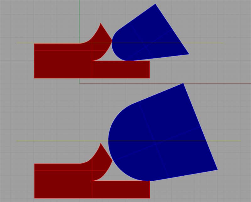
I like to use this diagram to explain rubbing:
The endmill at top is cleaning slicing up chips. The one on the bottom is rubbing.
In the diagram, the endmill at top is cleaning slicing up chips while the one on the bottom is rubbing. The difference is the relationship of the radius of the cutting edge to the chip load. Chipload is the tickness of the chip. You can literally measure the chip load by measuring chip thickness. If the chip thickness is too small relative to the cutting edge radius, the top of the chip falls below the centerline of that radius. That centerline is the yellow line in the diagram.
When that happens, the edge can’t get under the chip–the curve of the edge forces the chip down, not up, when it’s below the centerline. So what happens is the edge rubs along on top of the material heating things up like crazy from increased friction. Eventually it will drag a chip up, but it’s not nearly as efficient as normal chip formation and it heats up the tool far more instead of carrying the heat off in the chip.
This is not a happy thing, because too much heat will soften the tool. Once softened, it can no longer hold a keen edge, the tool dulls, and the rubbing problem becomes even worse. It’s a vicious cycle that does not end happily. The tool lasts a little longer than running way too much chip load, but in the end, it succumbs to an early death.
Clearly, rubbing is to be avoided no matter what. But sometimes it will sneak up on you. Sometimes the simple chip load formulas tell you chip loads are higher, perhaps much higher, than they really are. This comes about through a variety of geometric effects, but the most common one is called Radial Chip Thinning.
Rubbing Can Sneak Up On You Because of Radial Chip Thinning and Other Geometry-related Issues.
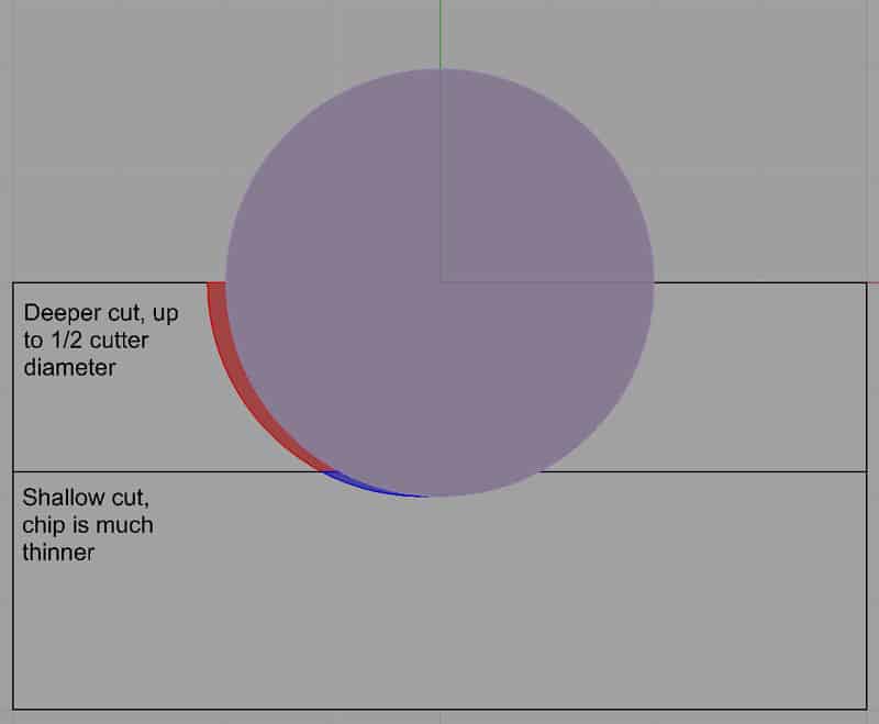
Any time you run the cutter with a cut width that is less than half the diameter of the cutter, there will be some radial chip thinning. The cutter will make thinner chips than simple formulas predict. This diagram shows why:
Yikes! Here we were thinking that taking a very light cut would be very conservative and instead what we’re doing is causing too little chip load (due to chip thinning) and therefore rubbing.
There are other variations on this theme. For example, if you have a face mill that is not a 90 degree (square shoulder) face mill it has a lead angle. The lead angle causes effects not unlike thinning too.
So What’s Poor Goldilocks to Do? How Can She Get a Steady Diet of Just Right Feeds and Speeds?
Goldilocks has some options. Some work and some don’t. Let’s consider what doesn’t work first.
You can hear Really Bad Feeds and Speeds but not Good Feeds and Speeds
She can’t just train her ear to hear “good” feeds and speeds. If she could, there’d be CD sets you could buy for machinist ear training. Shops would put headphones on new applicants and ask them to judge a cut by its sound. It just doesn’t work despite however many Old Timers who claim they can hear a good cut. The reality, is you can hear a really bad cut, but most can’t hear a modestly bad cut let alone tell the difference between a mediocre cut and a really optimal cut. Forget about it Goldlilocks, even your perfect pitch hearing won’t help you as a machinist.
Simple Formulas and Spreadsheets Aren’t Enough
Goldilocks can’t rely on those super simple feeds and speeds formulas that seem so easy to punch into a calculator or spreadsheet.
You can’t rely on simple feeds and speeds formulas…
Those formulas will tell you just enough to be dangerous as they don’t factor in all sorts of adjustments and over simplifications. There’s no allowance here for chip thinning, for example. And they don’t even begin to talk about things like HSM toolpaths, Tool Deflection, or the effects of High Pressure Through Spindle Coolant.
Just to give you an idea, our G-Wizard Feeds and Speeds Calculator considers over 60 variables for each Feed and Speed Calculation it makes. If you work hard at gathering the formulas for all of these many effects to build one gigantic spreadsheet, it still isn’t enough.
The variables interact in very complex ways. Spreadsheets chain formulas forward, but they are lousy at solving and balancing for multiple variables. At best, they can do simple goal seeking which is pretty awkward and inconvenient.
Manufacturer’s Data Isn’t Enough Either
What about all those big tables in the Manufacturer’s Tooling Catalogs? Surely they can tell you everything there is to know, can’t they?
Well, sort of, but not really. If you think about it, a single table is capable of dealing with 2 variables–one along the rows and one along the columns. So for example, we will often find a table that lists chip loads with tool diameters across the top and material type along the side.
There’s just one problem–chip load depends on a lot more than those two variables. So, they will often give you a range of chip loads. How do you know where in that range your particular cut should be? Or, they’ll tell you to use a different table when slot milling than when doing other milling operations. And still, that’s pretty clumsy and doesn’t factor in the subtleties like chip thinning. Or the fact that there’s way more materials and alloys than those simple tables show. How do I adjust my feeds and speeds for thousands of specific materials?
How could you even begin to deal with the 60 variables G-Wizard does using 2 dimensional tables? My head hurts just trying to imagine it.
Your CAM Software Doesn’t Do the Trick Either
Think about those tables and their limitations. Most CAM packages treat Feeds and Speeds as nothing more than tables. The same arguments apply, and it’s a big reason why CAM feeds and speeds often produce poor results and almost never produce optimum results. Some CAM vendors, like SolidCam’s iMachining, realized this and invested heavily in creating “real” Feeds and Speeds engines for their software. The vast majority have not.
Okay Goldilocks, Here’s How You Get “Just Right” Feeds and Speeds All Day Long
Well you must have guessed how this story would end, right? To get Goldilocks Feeds and Speeds, you need a piece of software that’s specifically created to do the job.
Many machinists are working today without the benefit of such software, and they’re paying the price whether or not they know it. Getting high quality feeds and speeds is really pretty easy once you have a package like our G-Wizard. It’s chock full of power, from being able to analyze all those 60 variable together, trade them off, and find optimal combinations, to having a myriad of special sub-calculators that solve specific problems CNC machinists encounter constantly.
Quick, what are the maximum feeds and speeds I can run for this part on a vacuum table without popping the part off the table? G-Wizard can tell you that.
Join 100,000+ CNC'ers! Get our latest blog posts delivered straight to your email inbox once a week for free. Plus, we’ll give you access to some great CNC reference materials including:
Bob is responsible for the development and implementation of the popular G-Wizard CNC Software. Bob is also the founder of CNCCookbook, the largest CNC-related blog on the Internet.