Are you facing a difficult task, perhaps due to your machine being too light or because the part geometry presents a challenge (for instance, deep pockets)? Or could it be because of a hard-to-machine material such as Titanium? If that’s the case, Plunge Milling (also referred to as Plunge Roughing) might be the solution.
Plunge Milling is a type of CAM Toolpath, though it can be programmed manually as we will see. The idea, is to rough out a pocket, profile, or 3D surface by plunging either a twist drill, an endmill, or a special-purpose milling cutter straight down into the material.
Here’s a typical example:
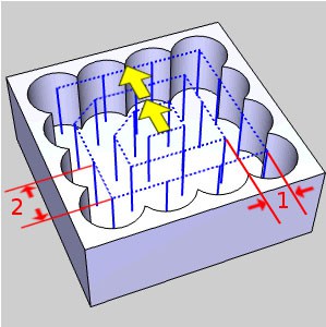
Plunge Milling a Pocket – Image courtesy of BobCAD…
The graphic shows a typical plunge milling operation for a square pocket. As you can see, a chain of holes are plunged vertically with the milling cutter to rough out most of the pocket area. A subsequent finish pass will complete the pocket.
I called Plunge Milling a “Secret Weapon” above because it can really save your bacon in some situations. It is designed to take advantage of two important properties:
Twist drills often have much higher material removal rates than endmills.
Most CNC Machines have Z as their stiffest axis. By changing forces from side forces (XY plane) to axial (Z) up and down forces, we get much more rigid cutting.
Taken together, it’s pretty easy to see where Plunge Milling could turn into your Secret Weapon.
Perhaps you have a relatively lightweight or less rigid machine. By taking advantage of the greater rigidity your machine will have in the Z direction, you may be able to get higher Material Removal Rates. Or, you may be able to overcome a chatter problem that’s due to a lack of rigidity.
Older (or cheaper) CNC milling machines that have more slop in the XY axes, less precise interpolation, or slower spindle speeds may also benefit from exercising the Z-axis more via Plunge Milling. Plunge Milling seems tailor-made for the limited rigidity and performance of Hobby CNC machines too, for example.
How about a Mill-Turn situation where your live tooling is not nearly as rigid as on a pure milling machine? Here again, you may find Plunge Milling is just the ticket.
Plunge Milling can also be just the ticket when your machine’s spindle power is limited, according to Sandvik.
Talk about a lack of rigidity–long reach and thin walls make Plunge Milling a natural for this 5-axis turbine application. Image courtesy of Hypermill.
Another way Plunge Milling can help overcome a machine’s limitations is when spindle speed is limited. Plunge Milling Feeds and Speeds may be a little slower than straight up high speed machining. But, if your spindle rpm is the limiting factor, you may not be able to take full advantage of HSM. If that’s the case, Plunge Milling is even more likely to give you the best Material Removal Rates.
How about machining a tall thin wall? This is a notoriously chatter-prone situation that may be partially amenable to Plunge Milling. It’s not a total cure, because you’ll still have to manage a finish pass that removes the scallops, but it might allow higher Material Removal Rates without chatter for the roughing pass.
In fact, consider a Plunge Milling tool path any time chatter becomes a big problem on a job.
One last special case for Plunge Milling would be corner clearing. When the depth of the corner is greater than about 4 x the cutter diameter that fits into the corner, rigidity issues develop.
Aside from special cases, some shops report that Plunge Milling allows them to do roughing on older machines in the shop that might otherwise go unused. They keep their newer machine centers busy on jobs the older machines can’t do, and over shop spindle utilization goes up. That means more profit.
I like the idea of Plunge Milling for Lights Out Machining too. It seems inherently more conservative and less prone to problems like whether coolant is aimed properly or not.
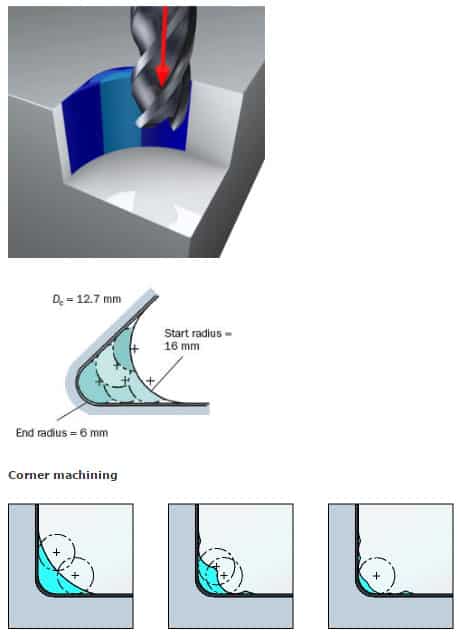
Plunge Milling can be applied to help maintain rigidity in these difficult cases:
Plunge Milling Corners. Image courtesy of Sandvik.
One could imagine doing most of the roughing with an HSM Toolpath and an endmill that is much to large in diameter to get into the corners. Depending on pocket shape, this can clear most of the material without leaving much scalloping.
As part of the final finish or an intermediate Semi-Finish pass, we use a much smaller diameter endmill to clear the area of the corner and then we can make an overall finish pass of the entire wall of the pocket or profile.
Plunge Milling Disadvantages
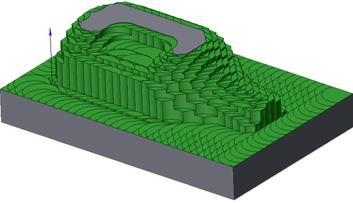
Plunge Milling leaves scalloped edges which may take a fair amount of cleanup or a semi-finishing pass before a true finish pass can be applied. Image courtesy of Sandvik-Coromant.
Scalloped Edges: Plunge cutting leaves a scalloped edge (see diagram above) that will have to be cleaned up by a finish pass. Depending on your X and Y stepover amounts, the amount of scallop to be removed could be significant. If it’s more than a single finish pass can remove, an optional semi-roughing pass will be needed to clean up the scallops before the final finish pass can be applied.
Center Cut: The tool used must either be center cutting (leaves out many types of indexable endmill) or the toolpath must allow for a ramp or helix entry to create enough space to start taking partial plunge cuts. If the tool isn’t center cutting, it also can’t cut on a down slope where the feature gets deeper in some places.
2D vs 3D Plunge Milling: Some Plunge Milling toolpaths only support 2D features where the floor is at the same Z, while others can do full 3D Profiling via Plunge Milling.
Conventional Twist Drills: The point angle on conventional twist drills makes them wander when plunge roughing if the holes overlap too much. You also wind up with a scalloped floor, which is less desirable. This may require flat-bottom tooling such as endmills or twist drills that are specially made for Plunge Milling.
Not the Best Under Favorable Conditions: Plunge Milling is not a general-purpose strategy that replaces all other strategies. It’s best use is when you need Plunge Milling’s advantages: more rigidity and less power required. If those are not problems you need to solve, then Plunge Milling is probably less optimal than other Roughing Strategies such as a High Speed Machining (HSM) Toolpath.
Plunge Milling Feeds and Speeds
Our first task is to decide on the X and Y stepovers.
Sandvik recommends starting with a stepover (Cut Width in G-Wizard) of 80% of cutter diameter for the sideways motion of a single pass.
The stepover to move deeper into the material for the next pass is limited by the insert diameter or the maximum Cut Width of any non-center cutting tool. 80% of that value is a good choice as well. Keep an eye out so there’s no skinny stalks sticking up in the corners between the holes. If you see stalks, you need less stepover in one dimension or the other.
Let’s work through an example that shows the strengths of Plunge Milling. Suppose we are handed the task of roughing out a pocket that has 1/8″ corner radii, which dictates and endmill no larger than 1/4″ in diameter. Next, suppose that pocket is 1 1/2″ deep.
I can already hear the groans out there in the audience–a pocket that deep with such a small endmill is likely to be a bear!
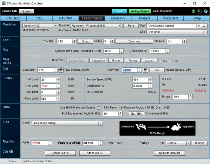
Just to keep things simple, I’m going to choose X and Y stepovers of 0.0625″ for this job. Let’s check Feeds and Speeds with G-Wizard and assume we want to use an HSM roughing strategy like Adaptive Clearing or Volumill:
MRR isn’t bad at 3 cubic inches/min, but deflection is way too high…
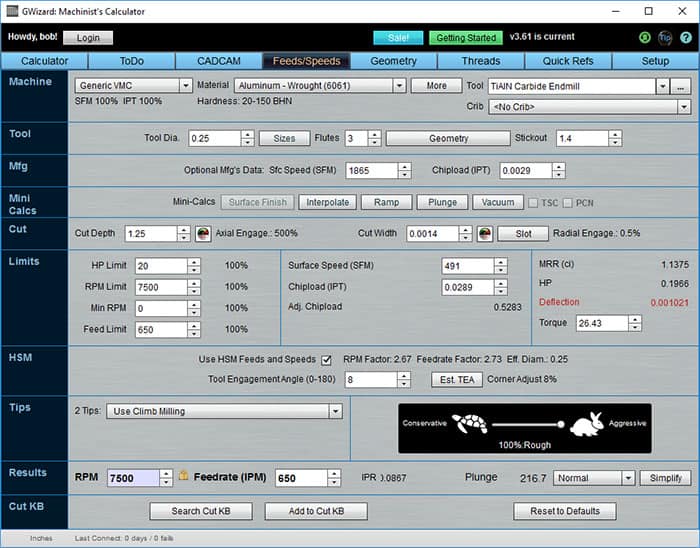
We can use G-Wizard’s Cut Optimizer to see how much stepover is allowable to keep things within deflection allowances:
Cut is almost impossible without too much deflection…
A quick click on the “Cut Width” label has Cut Optimizer taking us all the way down to a Cut Width of only 1.4 thousandths and there’s still a bit too much deflection. We could probably live with that, but MRR is down to a lousy 1.1 cubic inches a minute.
We’re going to lose our shirts on this job if we don’t find another way. What about Plunge Roughing?
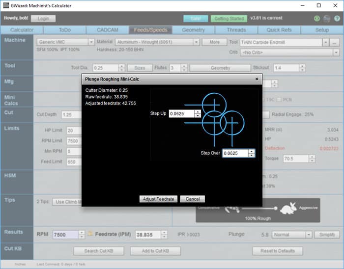
Click the “Plunge” button to bring up the Plunge Milling Mini-Calc:
G-Wizard’s Plunge Milling Calculator…
G-Wizard’s Plunge Milling Calculator let’s us enter a Step Up (amount to move into material at start of each pass) and a Step Over (amount to move laterally from prior hole on the same pass) and adjusts the feedrate based on those parameters.
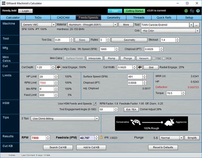
Here is the result:
Here’s a case where Plunge Milling shines…
Here’s a case where Plunge Milling shines: our MRR is back in the 3 cubes a minute territory of the original HSM scenario, and while the Deflection error is still red, we can ignore it because we’re plunging and there will be no significant deflection while doing that.
Problem solved!
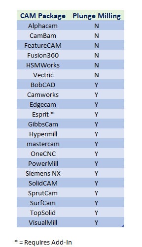
Which CAM Packages have a Plunge Milling Tool Path?
Here is a list of the most popular software from our last CAM Package Survey that shows whether each package has Plunge Milling or not:
As far as differences in Plunge Milling toolpath quality, it’s worth checking on whether your CAM package supports two capabilities.
First, does it do true 3D or just 2D Plunge Milling? 3D is obviously much more general while 2D will only work for flat-bottomed features.
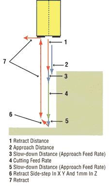
Second does the plunge cycle retract away from the wall during the overall retract? This reduces chatter and increases tool life when machining tough materials. Here’s the Plunge Rough retract style jointly developed by WorkNC and Ingersoll:
Retracting from the Wall slightly during Plunge Rough…
What Can I do if my CAM Software won’t Plunge Rough?
Normally if your CAM software doesn’t support a particular kind of toolpath, you’re just out of luck. But Plunge Milling may be different, depending on how adventurous you are. A basic strategy for creating your own Plunge Milling toolpath works like this:
Use your CAD Software to generate a grid of holes (circles or whatever you like) within the contours of the pocket or other feature’s outline. Be sure to leave some finish allowance, so you may need to inset the outline by the finish allowance. Depending on how easy it is to keep the circles entirely within the outline, you may have to inset further to leave enough allowance. Your CAD software does most of the work, so you’re relying on its sophistication to pull off the creation of the hole grid. Even if the package is a bit weak in this area, most of them should be able to lay down a grid within a rectangular region or perhaps in a line so you can Plunge Mill a slot.
Given the grid of circles, you create a g-code program to plunge the cutter at each circle’s coordinates. This can be as simple as taking a canned drilling cycle and feeding it the list of circle coordinates.
There are certainly embellishments. For example, you could do the fancy wall retract move with a little bit more hand coding. You may also need to deal with entering the pocket, though you could use just have your CAM package generate its entry and then cut and paste that gcode to create a starting point for your Plunge Milling routine.
With a little bit of gcode programming familiarity and some decent chops with your CAD software, this is not hard nor does it need to take very long.
Here’s an example I partially worked through in Rhino3D:
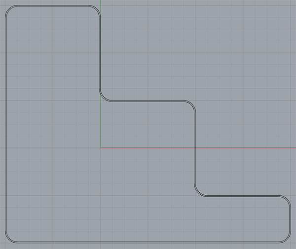
Start with the outline of your pocket. Inset that outline by a finish allowance. Here is the contour with an inset:
The contour of a pocket wall with an inset for a Finish Allowance…
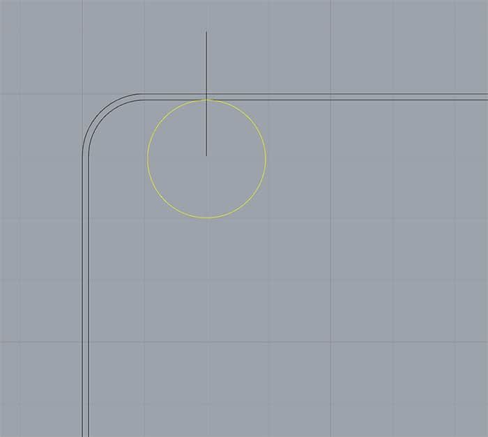
2. Drop a circle of the endmill’s diameter down and make it tangent to somewhere convenient on the inset contour:
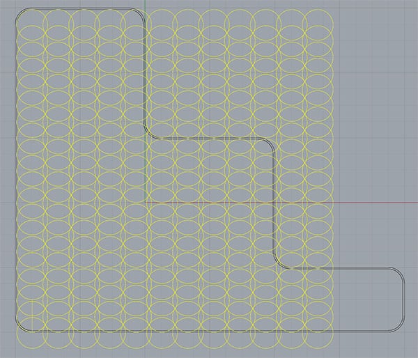
3. Create an array of the circles with the X and Y stepover you want to use:
I didn’t get the grid quite large enough!
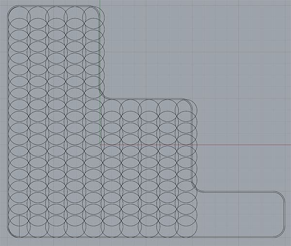
4. Trim any excess circles that extend too far out-of-bounds:
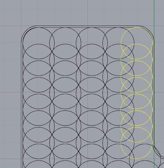
5. Adjust remaining circles at the edges so they’re tangent to any inset contour edges they intersect:
That’s about all there is to it. You now have a CAD drawing that shows where the holes for the plunge strokes need to go.
Import it into your CAM package and treat just like trying to drill all those holes. It’ll generate the gcode which you can then further tweak as needed.
I didn’t finish with the CAM part, but the CAD work only took 10 minutes and I didn’t use any shortcuts. It’s not hard to do if you want to play with Plunge Milling a bit. Programming something like this to clear a corner or two would be even easier.
Plunge Milling Cutters
You have multiple choices of cutter when Plunge Milling:
Conventional End Mills and Indexable Tools
Twist Drills
Specialty Cutters made for Plunge Milling
G-Wizard makes it easy for you to evaluate which one will perform best for your jobs given all the variables that are in play.
While on the subject of Copy Mills, they convert most of their cutting force to the axial direction, so are ideal in cases where your CAM doesn’t support plunge milling.
One thing to be careful of when Plunge Milling is any cutting near the center of the tool. Many indexable tools can’t cut in the center and many end mills are also not center-cutting. That means you’ll have to plan your stepovers so no center cutting is called for. You may need to create a starter hole with a drill (indexable or otherwise) to avoid center cutting issues.
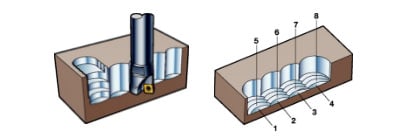
Plunge Milling with Twist Drills: Chain Drilling
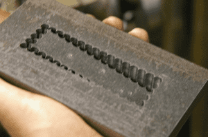
Back in the days of Manual Machining, chain drilling was pretty common with tough materials:
Image courtesy of Home Shop Machinist…
The technique worked and allowed a Bridgeport to open up a lot of material quickly. But, there are disadvantages. Twist Drills don’t like overlapping holes and interrupted cutting too much, so mind your stepovers accordingly. No more than 40% overlap can be tolerated if the drill has a conical point, and even this much can lead to a lot more wear. This may or may not lead to good Material Removal Rates, so this is another case where experimenting with a few scenarios in G-Wizard can really help refine your approach. Also carbide twist drills don’t like the shock associated with plunging too much. HSS or indexable tooling may be a better bet.
Another issue with Twist Drills is the holes are not flat bottomed. There are versions available that are flat bottomed, both indexable and solid, so consider those. Otherwise, you either want a through situation (a hole not a pocket) or you’ll have quite a lot of finish work to do on the scalloped floor of the pocket.
Most face mills have no cutters in their center, so they can't do a full diameter plunge. However, they may be able to plunge just a partial diameter that is covered by their available inserts.
CNC Plunge Milling is the process of plunging the cutter repeatedly into the workpiece to rough it out. It takes advantage of the fact that the Z-axis is often much more rigid than the X or Y axes.
I want to know more!
Like I said, Plunge Milling can be a powerful secret weapon in your CNC arsenal. It’s still not in wide use, so your competition may not have this secret weapon. We’ve seen its advantages graphically via G-Wizard in the case of a pocket that’s too deep relative to tool diameter.
Do you use Plunge Milling? Tell us your experiences and thoughts on Plunge Milling in the comments.
Like what you read on CNCCookbook?
Join 100,000+ CNC'ers! Get our latest blog posts delivered straight to your email inbox once a week for free. Plus, we’ll give you access to some great CNC reference materials including:
Bob is responsible for the development and implementation of the popular G-Wizard CNC Software. Bob is also the founder of CNCCookbook, the largest CNC-related blog on the Internet.