Thus, you’ve settled on procuring a new VMC for your workshop, potentially as an enhancement to a current machine, a substitute, or maybe this will represent your workshop’s inaugural VMC. Congratulations and sympathies are in order. My sympathies, because you are confronted with a bewildering variety of data that you must navigate in order to make the most optimal decision for your enterprise. The aspects you need to consider include:
– Work Envelope
– Spindle Power
– Spindle RPM
– Spindle Taper
– Rapids
– Rigidity and Vibration Dampening
– Availability of Support Nearby
– Ease of Use of the Machine’s Controller
– Compatibility with your existing tooling and best practices
And a whole host of other factors, many of them subjective or intangible. I’ll leave you to your checklists and selection matrices for many of these factors, but I wanted to walk through how you can use our G-Wizard Calculator and G-Wizard Editor to help do some fairly analytical evaluation on some of these factors. It’s actually pretty simple to do. Remember, G-Wizard Editor is essentially a CNC Simulator. What we’re going to do is use it to simulate two different machines so you can get an idea of their relative performance in real world terms that will matter to you and your shop. Let’s take it in steps.
Step 1: Build Your Evaluation Scenarios
You’ll need to start with a set of evaluation scenarios. These are test cases that are similar to your shop’s every day work. What you need are the part programs for some parts that are typical of what you make. The more the merrier, but 5 or 6 that span the gamut of projects you’ve undertaken and that you think are representative of projects your shop will undertake in the future will serve. You’ll want to take those 5 or 6 programs and think about the materials your shop will primarily be working with as it makes a big difference. Most likely you’ll have some softer materials like aluminum or plastics and some harder materials like steel or titanium. Try to get the part programs you use as test cases to mirror the types of materials you use, if possible. Ideally you’ll want 5 or 6 programs in each material, but do the best you can.
For this article, we’ll just use the HomeSwitchRearPanelEngrave.ncc sample program from our sample files for GW Editor. That file is set up for a retrofit milling machine I built that has a very slow spindle. I modified it to compare the following scenarios:
– Tormach 1100: Great entry level CNC mill
– Tormach 1100 w/ Toolchanger
– Haas VF-1
– Fanuc Robodrill
Step 2: Set Up Your Simulation Spreadsheet
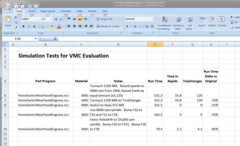
I just put together a very simple comparison spreadsheet in Excel that looked like this:
As you can see, I track what each scenario consists of in terms of part program, material, what I changed from one to the next, resulting simulated run time, time in rapids, time in tool changes, and the % overall run time versus the original. Depending on what you’re trying to figure out, a number of other columns might make sense.
Step 3: Set Up Machine Profiles for Each Machine You’re Considering
Each of these machines, the Tormach, the Haas VF-1, and the Fanuc Robodrill are quite different, but there’s plenty of data available online to set up a Machine Profile in the G-Wizard Software for each one of them.
Step 4: Calculate Feeds and Speeds and Adjust By Machine
The biggest difference in performance for these sample scenarios is spindle rpm, although tool change and rapids also play a role. I used GW Calculator to update the feeds and speeds for each scenario. For the 24,000 rpm Robodrill, I used a TiAlN carbide EM instead of the carbide EM used on the others. Some advantage could be gained for the others from the TiAlN, but it would largely be due to the higher chip loads more premium endmills allow. For aluminum, both the Tormach and the VF-1 are topped out on spindle speeds already. GW Calculator will tell you when it hits a limit like that, and I wanted to plug in some higher speed spindles just to show how much it matters for a material like aluminum that can be machined at very high spindle speeds. If you’re working something a lot harder, the higher spindle speeds might not even be usable.
Step 5: Run the Simulations
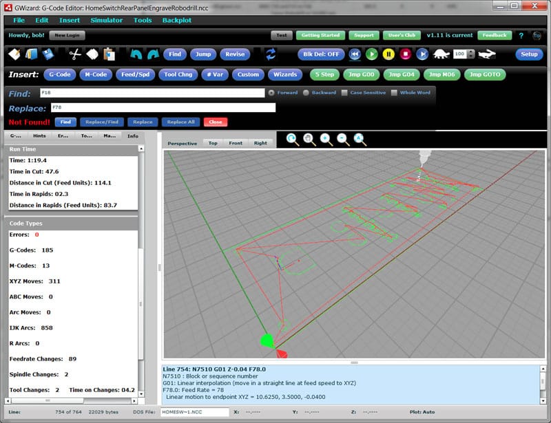
To run the simulations, I used the GW Editor’s Find/Replace function to update the Feeds and Speeds in the program, I put the correct machine profile in place, then I went over to the Info tab and recorded the results in the spreadsheet. The Info Tab collects all sorts of information about the running characteristics of the simulated part program:
Evaluating the Results
The spreadsheet tells the story of this particular set of scenarios. Adding a toolchanger to the Tormach saved almost 20%. Switching to the Haas VF-1 got us another 20% without updating the program largely due to faster rapids. Updating for the VF-1’s base 8K rpm spindle got us to a more substantial 43% savings–almost twice as fast. The Robodrill’s 24K rpm spindle really sings, though, as it manages an 85% savings in cycle time.
None of this is to say that any of these machines is better than the other–these are just the results of one particular set of scenarios. For example, there are materials that have to be cut slowly enough we couldn’t take advantage of the 24K rpm spindle option on the Robodrill. Perhaps they can’t run the spindle any faster than the Tormach’s, but these difficult materials might require more rigidity. What you’ve got to do to make a business decision is build a good set of representative scenarios for your shop or project, plug in the cost information, and then see how long it would take to pay for the investment in better machinery.
These have also been very simple scenarios. We only used one sample part program and the nature of the program (aluminum panel engraving) really favors a machine like the Robodrill. There’s a reason they use little mills like that to make things like Macintosh laptop chassis. Consider some other kinds of scenarios you could simulate. For example, work envelope. A bigger machine will let you run more parts in a single setup. You can even simulate software advantages. How much will that new CAM software with the HSM toolpaths speed up your jobs? For a quick and dirty answer, use G-Wizard Calculator to figure a new set of feeds and speeds and plug those into a part program for simulation. It won’t be exactly right because the toolpaths will change, but it’ll be in the ballpark and will give you an idea of how long it’ll take you to pay off that new software.
Join 100,000+ CNC'ers! Get our latest blog posts delivered straight to your email inbox once a week for free. Plus, we’ll give you access to some great CNC reference materials including:
Bob is responsible for the development and implementation of the popular G-Wizard CNC Software. Bob is also the founder of CNCCookbook, the largest CNC-related blog on the Internet.