This week, we’ll delve into the 3D printing software tool chain, focusing predominantly on Open Source software that is commonly used across various operating systems like Windows, Mac OSX, and Linux.
The 3D printing software tool chain begins with CAD to create the 3D model. Most of the commercial and Open Source CAD software packages are used to create 3D models for CNC milling can be used to create 3D models for printing. The only significant requirement is that the CAD software has the ability to save or export the design as a 3D mesh STL (STereoLithography) file. Some common Open Source cross-platform products used by the RepRap 3D printing community include:
OpenSCAD takes a very interesting approach and has become quite popular. Rather than draw your model with graphics tools, you define the model in a scripting language and then compile the script into the 3D model. These scripts can be parameterized to make it easy to scale and modify models. Blender is also a very popular Open Source option.
One important aspect of 3D modeling for 3D printing is being aware of model design constraints. For instance, overhangs greater than 45° are difficult/impossible to print without support material (an advanced operation). Here is a shot list of common design constraints:
objects must be manifold – in a nutshell, this means that edges in the 3D mesh must not be shared by more than 2 faces.
no floating objects – the object must sit on the Z=0 plane
no overhangs greater than 45°
tall thin walls are difficult to print
avoid large unsupported bridges, like those across holes or an unsupported top surface
If 3D design is not your forte, don’t despair, there are 10,000s of free, printable STL files available on Thingiverse.com. Not only are these objects ready to print, they are a great source for ideas or starting points for your own designs or modifications.
3D Model to 3D Object: Slicing
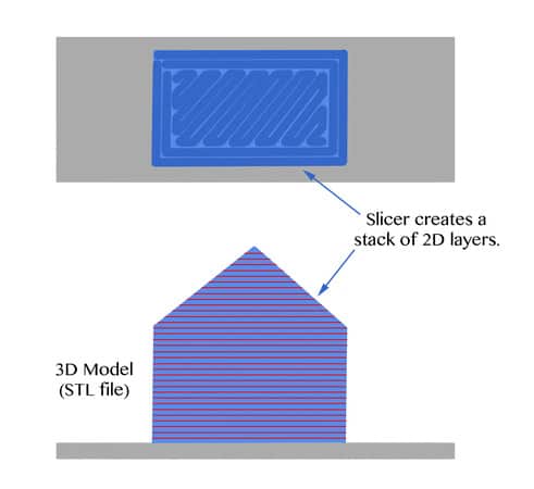
The software component known as a “slicer” in the 3D printing world takes the place of the CAM component in CNC machining. It’s job is to convert the 3D model – described in an STL file – into the g-code that is interpreted by the printer’s controller (more on this later). Conceptually, the slicer slices the 3D model into 2D layers, each the height of the extruded filament. Then, a tool path for each layer is calculated based on extrusion diameter, fill pattern and other factors. Extruder movements are also created along with the X-Y positioning of the nozzle. The diagram below shows how a model (described in an STL file) of a simple house is sliced into multiple layers (red lines) and a tool path is calculated for each layer. The tool path traces the perimeter of the layer and then infills it, in this case with a solid diagonal infill pattern.
The Z height for each layer is constant. Once a layer is complete, Z is raised to the next layer and the process repeats to stack a new layer on top of the previous layer. In this way, the 3D object is built up of 2D layers. Slicers also insert code to set the hot end and heated build platform temperatures and turn on and off fans. Slicing is a complex process that needs to know details like nozzle diameter, plastic material melt temperature, rapid speeds, and extrusion speeds to list a few. This software is evolving rapidly to add new features to control the printing process. Sophisticated anti-blobbing and stringing features are particularly useful. Some of the most common Open Source slicers include:
Now that you have a 3D model (CAD) and sliced it into g-code (slicer) and have configured and uploaded your firmware to your Arduino based controller, you need one final software application to make a print. This is called the “host” application and provides the user interface for the basic operations to upload g-code files, turn on and off the printer, and start and stop printing. Host applications also are rapidly evolving and sometimes blur the lines between “host”, “slicer” and even “CAD”. A few options include:
Proterface is a simple but stable and configurable Python application. Repetier host is an interesting application in that it integrates a slicer (either Slicr3 or Skeinforge) so you can slice and print from a single application. It also has an advanced feature when used with the mating Repetier firmware (see below) – configuration parameters that are saved in EEPROM. This allows you to adjust printer settings without recompiling and uploading firmware. Cura also integrates with a slicer and provides a sophisticated host environment. New to the host scene is OctoPrint. This host is a web-based application that allows you to control your 3D printer over the network from a web browser. This is a very cool idea and OctoPrint is gaining a lot of popularity.
3D Model to 3D Object: Firmware
As mentioned in Part 3: Electronics, the most common 3D printer controllers are Arduino based. These controllers are powered by firmware developed in the Arduino IDE. The firmware is responsible for translating the g-code file generated by the slicer into the actually electronic signals that move the X, Y and Z axes, the extruder, turn on and off hot end and build platform heaters and turn on and off optional fans. AS Open Source projects, there is a lot of sharing and reuse of code from one firmware to another. Some of the common firmwares are:
In addition to interpreting the g-code, the firmware also embeds all of the printer-specific calibration details. Unlike Mach 3, which uses configuration dialogs to create a config file describing the CNC machine, Arduino based firmwares actually compile that configuration into the firmware code itself (with the exception of Repetier which has an optional EEPROM mode for some settings). For instance, motion control calibration is determined and then set in the firmware to translate the requested move distance to the number of stepper motor pulses required to move that distance. Most of these firmwares provide a file called Configuration.h where this information is set.
Wrapping Up
To summarize, the 3D printing software tool chain looks like:
CAD -> Slice -> Host -> Firmware
Of course, if you start with a downloaded 3D model (STL file) from Thingiverse, you do not need to design your own objects in CAD. However, slicing is always required to created printer-specific g-code for your machine. The host application controls the printer and provides a user interface for loading g-code files and printing them. Finally, the firmware runs on the Arduino based controller and is repsonsible for converting the g-code into the signals that actually control the printer hardware.
This post wraps up the four (actually 5) part 3D Printing 101 Series. I have lots of material and ideas for future posts but if there is anything you’d like me to cover, don’t hesitate to ask![/et_pb_text][/et_pb_column][/et_pb_row][/et_pb_section]
Like what you read on CNCCookbook?
Join 100,000+ CNC'ers! Get our latest blog posts delivered straight to your email inbox once a week for free. Plus, we’ll give you access to some great CNC reference materials including:
Bob is responsible for the development and implementation of the popular G-Wizard CNC Software. Bob is also the founder of CNCCookbook, the largest CNC-related blog on the Internet.
Wow, talk about timely. I was just digging around and writing a bit about using SketchUp and Blender for the DIY CNC machinists out there.
Have only been following your blog for a few days but think it’s great. Hadn’t seen these yet but they look well researched and thorough. Looking forward to digging in! Thanks!