2 months by cncdivi
In this installment of 3D Printing 101 I am going to look at the mechanical aspect of a typical 3D printer. Before I jump in, I should say that there are many different additive manufacturing technologies (i.e. 3D printers) but this series will focus on plastic filament extrusion printers that are the most familiar to hobbyists. After this initial series, I’ll follow-up with a post on some alternative technologies and point our their similarities and pluses and minus as compared to filament extrusion printers.
>> 3D Printing 101: Part 2: Mechanics
3D Printing 101: Part 3: Electronics
3D Printing 101: Part 4: Software
A Little 3d Printer Math
Most readers of the CNCCookbook are familiar with CNC routers and milling machines that typically feature 3 axes of movement. These axes are orthogonal to each other and are labeled X, Y and Z. The math used to instruct the machine to move along these dimensions, say to cut a circle in aluminum stock, is based on
Cartesian geometry. Even though the math to describe arced and diagonal movements may be complex, the basic concept of Cartesian geometry is almost intuitive to most people.
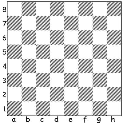
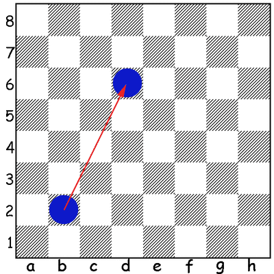
Consider the checker board shown below. In this figure, the columns (let’s call it the X axis) are labeled ‘a’ through ‘h’ and the rows (let’s call it the Y axis) labeled “1” through “8”. The movement of a checker on this board can be described simply by stating its starting and ending position as pairs of X-Y coordinates. In this example, moving the checker from (b,2) to (d,6) describes a linear path. It is a matter of convention as to which coordinate is presented first – in this case the X dimension – and all coordinate pairs should follow the convention.
This simple case of movement in a single plane can be applied to CNC plasma cutters or waterjet machines that cut 2 dimensional objects from flat sheets of stock. Axes for 2 dimensional movement are typically labeled “X” and “Y”. By adding a third, “Z” axis to move perpendicular to the X-Y plane, parts with 2-1/2 or 3D geometries can be fabricated.
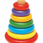
Note: 2-1/2D geometry is used to describe stacked layers of 2D shapes to create a 3D object. Printing on a 3D printer is actually 2-1/2D geometry since 2D layers of extruded plastic filament are stacked on each other to create the shape. The pyramid puzzle shown to the left is an example of 2-1/2D.
Basic Mechanics
Most desktop 3D printers are designed around Cartesian geometry, just like their milling machine kin. In fact, a CNC mill can be fitted with a “hot end” and extruder to create a 3D printer. However, since there are no “machining forces” when printing – for our purposes, the extruded plastic exerts no force on the machine’s structure as it is laid down – the mechanical structure of a 3D printer does not need to be nearly as rigid as a mill or router. The first
RepRap printers had a Tinker Toy-like appearance because they were fabricated from 1/4-20 threaded rod and simple connectors tying them together. This is still a popular design and construction. The framework, shown in the drawing below, supports the X, Y, Z positional mechanics and provides sufficient rigidity for the task of laying down melted plastic filament. Note the X and Y axes movements are left-to-right and front-to-back, respectively and the Z axis is the up and down movement.
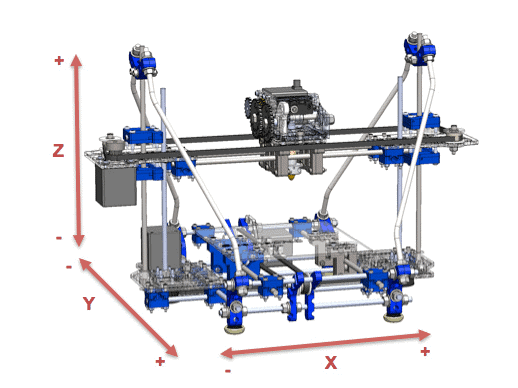
These mechanics will be familiar to CNC mill or router operators. Because there is very little mass to move, small NEMA 17 stepper motors and simple timing belts provide the motion control for the X and Y axes. Desktop inkjet printers also use small steppers and timing belts to achieve their remarkable positional accuracy and these work quite well for 3D printers too. Close scrutiny of the drawing above reveals that the Z axis is different – it uses screws to move along Z. Typically a low cost 1/4-20 threaded rod is used for this application. This results in much lower feed rates in Z as compared to X and Y but this is not normally an issue since movement along Z is incremental and one layer at a time from Z=0 (at the print table surface) to +Z as it moves up.
In addition to X, Y and Z motion control, 3D printers have several unique mechanical elements; a plastic filament extruder and a heated nozzle or “hot end”. Many printers also have a heated print bed to minimize part warpage and improve filament sticking to the bed surface. In the simple case, the filament extruder and hot end are combined into a single assembly. The extruder itself is stepper controlled and uses knurled rollers to grip the plastic filament in order to push it. The primary responsibility of the extruder is to move a calculated volume of filament into the hot end where it melts and then extrudes from the nozzle to build the layers of the printed object. The extruder/hot end assembly is usually mounted on a sliding carriage that provides movement in the X direction. The mass of the extruder is not usually problematic but can affect acceleration and speeds. The primary reason the Z axis is moved by screws is to accommodate this additional mass. The entire build table is moved for in the Y direction. The table itself is relatively light, even with a heater mechanism and large printed object on it, and does not require a lot of force to move. There are 3D printer arrangements similar to many CNC routers that use a moving gantry to move along X and Y and keep the print surface stationary. Both designs work well in practice.
An alternative arrangement to the combined extruder/hot end uses a
Bowden cable to transfer filament from a remotely mounted extruder to the hot end mounted on the movable axes. This arrangement reduces mass on the X axis carriage to allow higher accelerations and travel speeds. Bowden cables have a negative side-effect, they introduce a little backlash in the filament movement path which usually can be compensated for in software.
One interesting feature of 3D printing is that no “work holding” is required. There are no fixtures, jigs or clamps. The first layer of the printed part is actually “stuck” on to the build surface. Additional layers are applied to build up the 3D geometry. Getting this first layer of plastic to stick properly and not peal up during a print is the source of much frustration to many beginners. I’ll discuss this and techniques to get good first layer sticking in a future post.
Wrapping Up
To summarize, a typical 3D printer uses Cartesian geometry to provide motion in the X, Y and Z directions, has an extruder for pushing filament through a heated nozzle assembly, the heated nozzle itself, and an optional heated build surface or “heated bed”. These are relatively simple and inexpensive mechanics that can be built with hardware store parts like threaded rods and screws, printed connectors for the framework (the blue parts in the diagram above), and printed extruder gears and parts. The electronics required to drive movement and melt the filament will be covered in the next installment of this series.
Later this week I’ll make a follow-up post to this one that describes a new development for 3D printer movement, the
delta printer made popular last year by Johann Rocholl.


I saw what looked like an error in the orientation of the y axis in the picture but reading the blog the table is moved in the Y axis and the extruder in the X and Z axes. Am I understanding this correctly and that the effective movement of the extruder head is in conventional Y direction as a result?
Yes, that is correct.